- #How to build a rentive on delay timer siemens step 7 how to#
- #How to build a rentive on delay timer siemens step 7 series#
#How to build a rentive on delay timer siemens step 7 series#
PLC learning series 7: Functional Block Diagram program, symbols PLC learning series 6: PLC process Scan basics PLC learning series 5: 8 Rules for ladder diagram programming
#How to build a rentive on delay timer siemens step 7 how to#
PLC learning series 4 : How a ladder logic diagram works? How to read ladder logic ?

PLC learning series 3: PLC Architecture and wiring of PLC PLC learning series 2: PLC programming languages PLC learning series PLC learning Series I: What is PLC? Functions of PLC Where ‘ T0 ‘ is the address of the timer and ‘ K ‘ is the constant term. The input timer address is shown as a general representation in Delta PLC (T0, T1, ……. You can use timer addressing from ‘ T0 to T127 ‘ for the WPLSoft program. Addressing format with the three status bits for timer instruction. The timer has the address between T4:0 and T4:255 for the AB PLC.

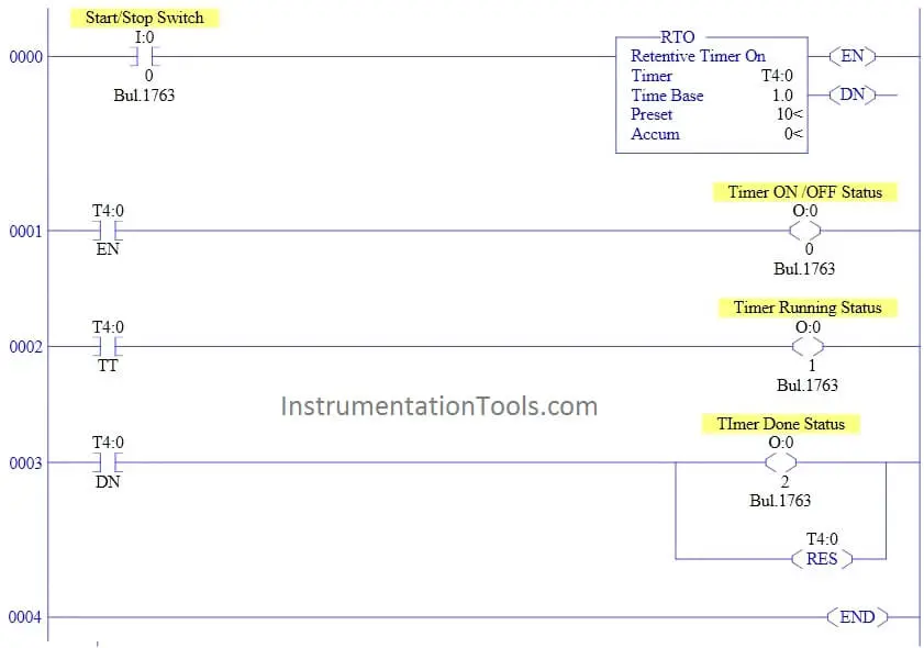
In the Siemens, LD program can be written with the five types of timers. We can set the value in T0 to T255 ranges. We can simply write the ladder diagram’s I / O address in the ABB PLC. And it indicates that the clock has reached its preset time. The output bit is often referred to as the ‘ Completed bit ‘ of the timer in the AB or Siemens PLC. The retentive timer must be reset with a different signal for the reset time. The timer’s power loss after reaching its preset value does not affect the contacts ‘ state. The reset instruction will be activated when its rung is true and resets the timer according to the address assigned to the reset instruction. When its rung goes from false to true, the Accumulate value of the retentive timer counts from where it stopped the last time. It is used when rung state change, power loss or any device interruption occurs. The RTO’s main function is used to keep or store the (accumulated) set time. When the accumulated value is equal to the preset value, the output turns off. The timer begins to work when the rung signal is false The timer continues to accumulate times until the accumulated value becomes equal to the preset value. The display will be ‘ on ‘ until the setting time is reached. When the off-delay timer (True) is energized in PLC programming, it immediately turns its output on.

The OFF delay means that it will change state a predetermined time after the timer has received the shutdown signal. When pre programmed time have passed with input S1 activated, the TR1 output is activated, energizing output PL1. The signal status of the output adjusts from 0 to 1 when the preset time is reached by changing the RLO (Result of logic operation) from 0 to 1(ON) at the starting input.įor example, When input S1 is activated, timer TR1 starts counting. The timer will be ON when a start input siganl is received, and when a preset timing is reached, the signal state of the output changes from 1 to 0. On delay means that once a timer has received a power on signal, its output will change state after a predetermined delay. You could set the PLC timer from millisecond (ms) to an hour (hr) time span in the programming of the Ladder Diagram (LD) PLC. When this time exceeds the programmed time then the timer activates its output. Simply, when the input is activated the timer starts its operation keeping track of the time.

The timer creates a delay in both PLC programming and in relay boards on connection or instantaneous disconnection.


 0 kommentar(er)
